
1. Introduction
1.1. Aircraft
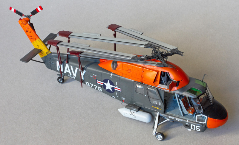
Kaman UH-2A Seasprite
Rescue and utility shipboard helicopter (information in Wikipedia)
U.S. Navy. BuNo 149778 / HU05. HU-2 squadron.
USS Forrestal (CV-59), at sea, 1964.

1.2. Story
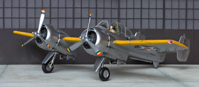
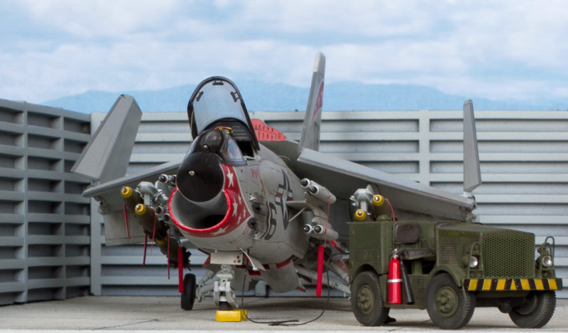
A UH-2A Seaprite of Utility Squadron 2 aboard the USS Forrestal supercarrier is being prepared for a routine "plane guard" mission. Flight deck crewmen begin to unfold the main rotor blades. An NC-1A mobile electrical power unit is standing by to start the Seasprite's engine later on.

1.3. Model Kit
UH-2A Seasprite from ClearProp (kit # 72002), 1:72 scale.
2. Kit Overview
The ClearProp team deserves immense praise for tackling a subject not previously "kitted" in any scale, presumably with rather limited reference material, and for bringing us a model with very good overall accuracy and commendable level of detail out-of-the-box.
Features like full cockpit interior, cabin doors presented as separate parts, well-detailed rotor heads and landing gear are noteworthy.
The quality of molding is generally good, yet the plastic is not without some glitches such as visible seam lines and slight misalignment of halves.
There are some accuracy issues, all relatively minor:
- The assortment of various antennas (bulges, blades, etc.) on the fuselage bottom is not entirely correct for the UH-2A/B variant.
- The blue of the U.S. national insignia is not accurate on the decal – it is too light.
- Incorrect or insufficient recommendations on painting / colors are given in the instruction booklet (I will address this in section 3.2 of my article).
3. Construction
3.1. Building

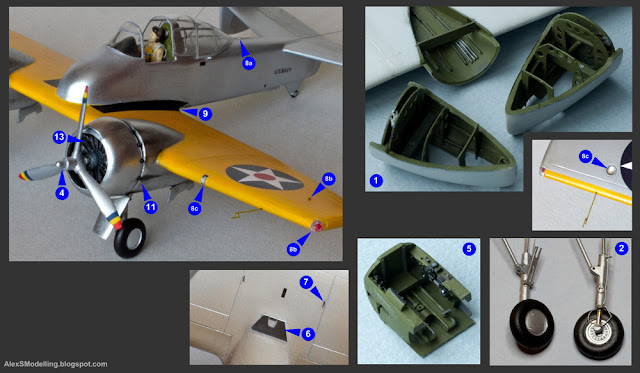
This is the list of enhancements that I have made to what was in the box.
Firstly, we have to address a number of minor inaccuracies of the kit:
1) The suit of antennas (bulges, raised panels, blades) on the fuselage bottom was corrected in accordance with historical photographs (such as this). I have sketched the correct configuration on a diagram given below.
2) Excessively sharp creases were smoothed on the landing gear forward fairings and along some bulges of the engine compartment.
3) Some spurious raised lines were removed from the left side of the aft fuselage.

Secondly, to get an accurately looking model you have to add a number of details – either simply too small to be molded in plastic, or just omitted in the kit:
4) The cabin interior is good out of the box, yet the webbed seats must be thinned and the area below the instrument panel needs more detailing as it is clearly visible through the lower cabin windows.
5) Several fuselage inlets and vents were cut out, with fine grilles placed over the openings where appropriate. Note that on the tail rotor shaft fairing the grilles must be vertical and not horizontal, as molded in the kit's plastic.
6) Some improvements had to be made to the landing gear wells to mask the excessively visible seams between the plastic parts that comprise the wells.
7) Brake lines were imitated on the main landing gear legs.
8) Fuel lines were added, connecting the fuel tank pylons to the fuselage.
9) Clearly seen gaps were ensured between the main rotor blades and their respective blade flaps, as it should be on a real Seasprite.
10) As usual, external lights required considerable attention. These included the following:
a) clear white navigation light and red anti-collision light on the tail rotor pylon fairing;
b) ventral anti-collision light, clear red;
c) a collection of four circular landing lights and floodlights in the lower forward fuselage, all clear white;
d) clear red and green navigation lights, teardrop shapes on small pedestals each side of the engine compartment.
11) Wire aerial was imitated. Normally it was stretched between the aft fuselage and the left horizontal stabilizer tip, but when the rotor blades were folded and their support rods were installed, it was apparently unhooked and hung along the fuselage side.

Finally, a fair amount of work was required to get the configuration that I wanted to have:
12) The early Seasprite's retractable rescue hoist is a unique feature, so I wanted to showcase it – by scratchbuilding the hoist in the deployed position, obviously. This necessitated the scratchbuilding of the interior that is left visible by the opened rescue hoist hatch, and that required way more work than the hoist itself.
13) As I intended to present my helicopter as being parked on the flight deck, the main rotor blades had to be folded, and required rotor blade support struts had to be scratchbuilt and attached.
14) The Seasprite's main rotor blades are folded and unfolded manually, and the groundcrew need access to the rotor head while doing so. To facilitate this, the engine bay side panels open as platforms. And one of these panels, on the left side, I wanted to showcase as open and ready for the rotor unfolding procedure. Which inevitable meant that I had to scratchbuild the interior, including a part of the turbine and respective driveshafts.


3.2. Painting & Markings
As a prototype for my model I wanted a colorful Seasprite – with bright Red Orange hi-viz markings – covered by at least one good and clear historical photograph, and therefore I selected the BuNo 149778 assigned to the HU-2 in 1964. Here's the photo: link.
Here are some guidelines applicable to the Engine Grey-camouflaged single-engine Seasprites:
- Interior: light bluish gray (most probably Light Ghost Gray); instrument panel: black; pilot seat cushions: orange-red; cabin webbed seats: khaki or light gray.
- Top cabin windows: clear green.
- Fuselage: Engine Grey (FS16081), with the following additional markings:
-- Wide Orange-Yellow (FS13538) band across the tail rotor pylon.
-- Between 1962 and 1965, Fluorescent Red Orange (FS28913) high-visibility markings were applied as follows: fuselage nose section, fuselage top section, tail rotor pylon (either full or from the Orange Yellow band upwards). From 1966 onwards, the Red Orange has disappeared from all "line" Seasprites (those serving in HU and HC squadrons that deployed on ships) and may have remained only on some of the shore station machines.
-- Alternating diagonal stripes in red and yellow on one or both of the horizontal stabilizer planes – from 1965 onwards, on some machines only.
-- Black anti-glare panel and "mask" around the front windows.
-- Thin white outlines around the side windows on some machines – seek reference photos for your BuNo.
- Wheel bay interior, main landing gear legs, wheel hubs: Insignia White (FS17875), most common by far, or Engine Grey – seek reference photos for your BuNo.
- Tail landing gear leg: Engine Grey.
- Antenna housings on the fuselage bottom: black, Radome Tan or Engine Grey – see my diagram for the most typical layout.
- Engine exhaust pipe: dull steel / burnt metal.
- Main rotor head and tail rotor head: Engine Grey (absolutely not "silver", as suggested by the kit's instruction).
- Main rotor blades, top: Light Gull Grey (FS36440) with aluminum leading edge separated by a very clearly seen longitudinal black stripe.
- Main rotor blades, bottom: black with aluminum leading edge.
- Tail rotor blades, from hub to tip: red band, then black, then red, white and red stripes.
- External fuel tanks: Insignia White or Engine Grey – seek reference photos for your BuNo.
It is worth noting that the U.S. Navy's Engine Grey is a "tricky" color. It looks quite differently under different lighting condition, and it appears that it also could change hue with weathering. Take a look at these historical photographs: photo 1, photo 2, photo 3, photo 4.
All these helicopters are absolutely standard and painted in the prescribed Engine Grey, although they look very differently due to lighting conditions and, possibly, due to different photographic film processing techniques.
Also note how on each of those photographs the Insignia Blue of the U.S. national insignia is invariably much darker than the Engine Grey of the helicopter fuselage. Which is as it should be – as opposed to the very light blue color that we see on the ClearProp's decal sheet (see, for example, here)
On my model, the national insignia decals came from a generic sheet by Techmod, while the rest of the markings are from generic Microscale decal sets. Only the small technical stenciling is used from the kit's decal.


Short articles in general reference books (e.g. "Illustrated Guide to Military Helicopters") and aviation magazines do exist. However, they do not usually spend more that a couple of lines on the early version of the Seasprite, concentrating instead on the SH-2F and G submarine hunters. So don't expect any service details, configuration notes, dimensions, drawings or photographs of the UH-2A/B in such books. Furthermore, you won't meet a single-engine Seasprite in any museum, and no walkaround-style photographs can be found. This is because, most probably, no single-engine Seasprites have survived: every frame was either converted to the later twin-engine version or lost in some accident.
Wikipedia article (already referenced above in section 4) offers a good overview of the Seasprite. Most of the other articles available on the Internet appear to repeat of rephrase the short excerpts from some of the general reference books, or simply to copy one another.
5.2. Like many aviation pioneers, Charles Kaman, the founder of Kaman Aircraft Corporation, strove to innovate. Although Kaman did not invent the intermeshing rotors, his helicopters utilizing this design were the first ones (and remain the only, as yet) to be in mass production and in successful operational service. As evaluation concepts, Kaman flew the world's first gas turbine powered helicopter (a modified K-225 model) and arguably the first unmanned helicopter. All of this is mentioned fairly often. But there is another innovation – not very important perhaps, but still curious – that appears to be forgotten: the Kaman UH-2A seems to be the first (and possibly the only) helicopter with a fully retractable rescue hoist (photo). Just like the retractable main landing gear, this feature was obviously incorporated to reduce drag. It did not survive for long, and the next variant of the Seasprite, the twin-engine UH-2C, was equipped with a conventional hoist, fixed externally. Yet the fact remains.


_on_6_June_1964.jpg)
_(26044118656).jpg)
.jpg)